Product Features:
1 Operating voltage: power supply 1,DC 6.5-25V; power supply 2,DC 5V
2 Operating Current: Standby current (all relays closed) 15MA, 1 relay open 45MA, 2 relays open 77MA, 3 relays open 109MA, 4 relays open 140MA
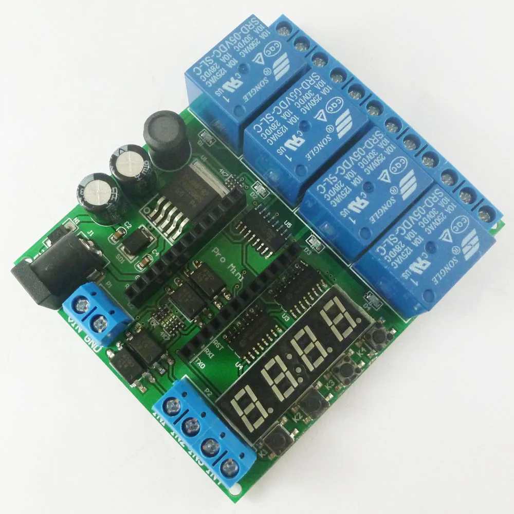
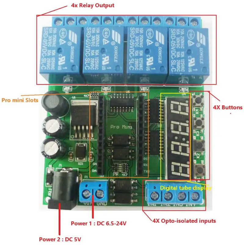
3 on-board resources: 4x opto-isolated inputs (low level trigger, NPN type), 4x buttons, 1x 4 bit digital tube display, 1 pair of Pro mini slots, 4x relay outputs
4 size 80*66*19mm
5 Weight : 79g
We provide the code(sketch) can only achieve a simple delay function,The delay time is adjusted by modifying the delay parameter of the code(sketch).
If you need more functionality, write your own code. We do not provide additional code(sketch) and technical support
How to use: See video '' IO22C04 pro mini delay relay demo''(You can search for videos on GOOGLE)
Note: IO22C04 can not work independently, must be under the control of the Pro mini board to work,If you do not have a Pro mini board, purchase it separately or purchase a kit with Pro mini
You may need:
Application examples:
As long as you write ARDUIUO Pro mini code(sketch),You can use it to achieve a variety of delay timer function,such as:
Motor forward and reverse,
Timing on,
Timing off,
Power-up delay,
Trigger delay,
Infinite loop delay,
A finite number of cyclic delays,
Power sequencer,
And so on.
Wiring diagram:
1 DC 6-24V control circuit,Wiring diagram below. ''LOAD'' may be LED lights, fans, motors and
other DC 6-24V equipment
2 DC 5V control circuit,Wiring diagram below. ''LOAD'' may be LED lights,fans, Development board and
other DC 5V equipment 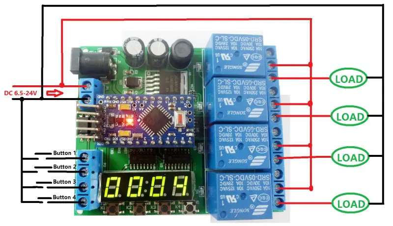
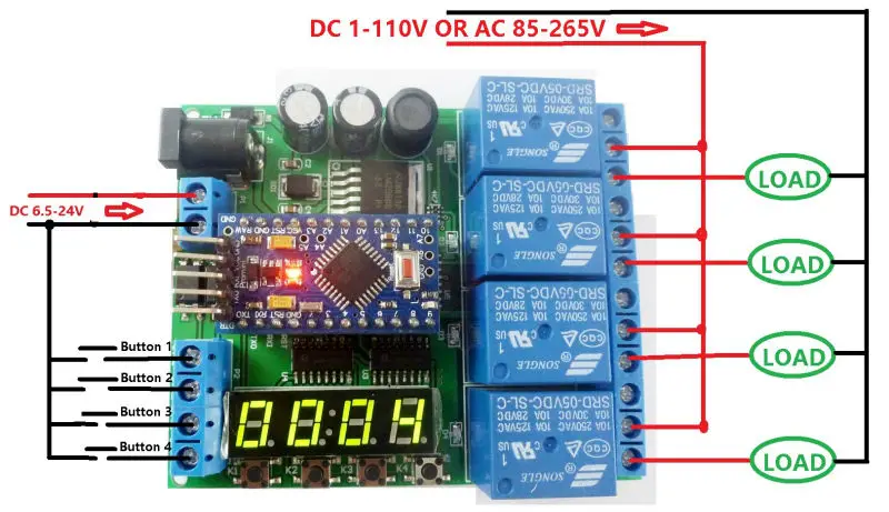
3 Power supply is 6.5-24V, ''LOAD'' may be DC 1-110V OR AC 85-265V equipment
4 Power supply is 5V, ''LOAD'' may be DC 1-110V OR AC 85-265V equipment 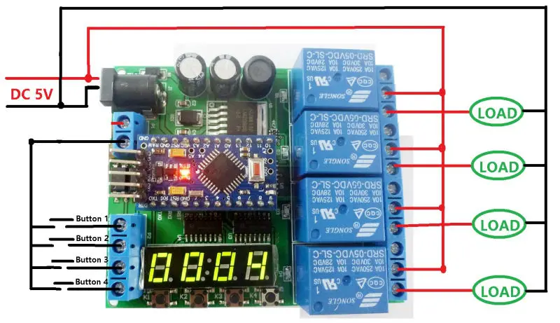
Product Name: DC 5V 12V 24V 4 CH Pro mini PLC Board Relay Shield Module For Arduino Delay Timer Switch
Package inlcuded:
1 PCS DC 5V-24V 4 channel Pro mini PLC relay board(Does not include Pro mini Board)
Product Features:
1 Operating voltage: power supply 1,DC 6.5-25V; power supply 2,DC 5V
2 Operating Current: Standby current (all relays closed) 15MA, 1 relay open 45MA, 2 relays open 77MA, 3 relays open 109MA, 4 relays open 140MA
3 on-board resources: 4x opto-isolated inputs (low level trigger, NPN type), 4x buttons, 1x 4 bit digital tube display, 1 pair of Pro mini slots, 4x relay outputs
4 size 80*66*19mm
5 Weight : 79g
We provide the code(sketch) can only achieve a simple delay function,The delay time is adjusted by modifying the delay parameter of the code(sketch).
If you need more functionality, write your own code. We do not provide additional code(sketch) and technical support
How to use: See video '' IO22C04 pro mini delay relay demo''(You can search for videos on GOOGLE)
Note: IO22C04 can not work independently, must be under the control of the Pro mini board to work,If you do not have a Pro mini board, purchase it separately or purchase a kit with Pro mini
You may need:
Application examples:
As long as you write ARDUIUO Pro mini code(sketch),You can use it to achieve a variety of delay timer function,such as:
Motor forward and reverse,
Timing on,
Timing off,
Power-up delay,
Trigger delay,
Infinite loop delay,
A finite number of cyclic delays,
Power sequencer,
And so on.
Wiring diagram:
1 DC 6-24V control circuit,Wiring diagram below. ''LOAD'' may be LED lights, fans, motors and
other DC 6-24V equipment
2 DC 5V control circuit,Wiring diagram below. ''LOAD'' may be LED lights,fans, Development board and
other DC 5V equipment
3 Power supply is 6.5-24V, ''LOAD'' may be DC 1-110V OR AC 85-265V equipment
4 Power supply is 5V, ''LOAD'' may be DC 1-110V OR AC 85-265V equipment